Self-acting temperature control system constructions
The required temperature for the system in Picture 7.2.1 is adjusted at the sensor. It is the most standard type of self-acting temperature control construction, and most other self-acting control designs are derived from it.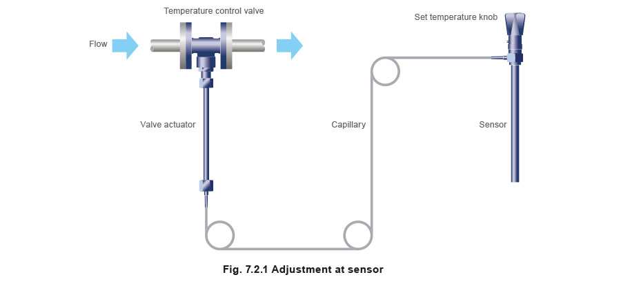
Picture 7.2.2 showcase a design which is adjusted at the actuator end of the system. It is worth noting that this system is limited to 1” (DN25) temperature control valves. This construction is useful where the control valve position is more accessible than the sensor position.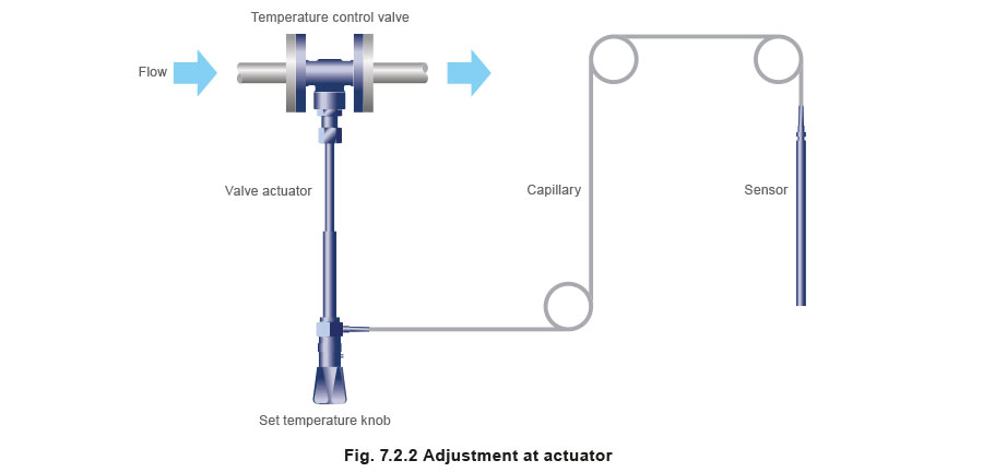
Picture 7.2.3 depicts a third construction which is similar to the one in Picture 7.2.1 however where the adjustment is located between the sensor and the temperature control valve actuation. This type of system is what we called a remote adjustment, and is useful when either the control valve or the sensor, or both, are likely to be inaccessible once the control valve has been installed.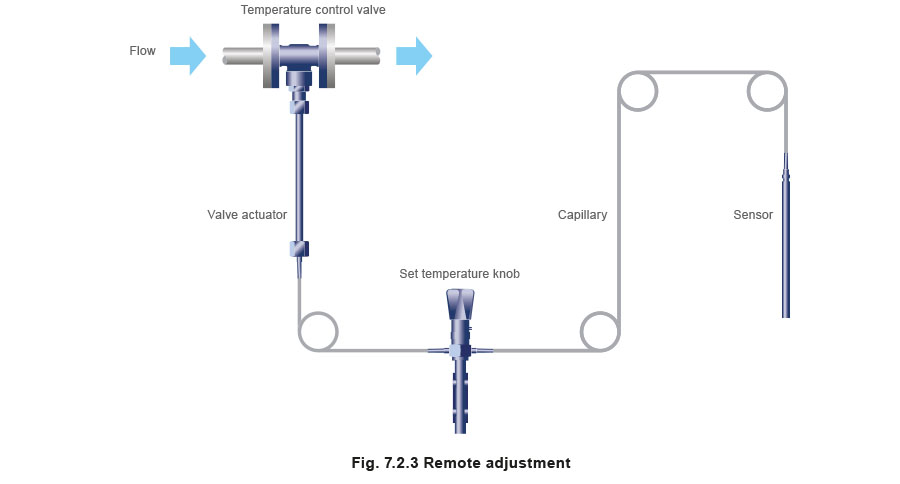
Capillaries
It should be noted that capillaries of 10 meters or more in length may slightly affect the accuracy of the control. This is because a larger amount of capillary fluid is subjected to ambient temperature.
When the ambient temperature changes a lot, it can affect the temperature setting. If long lengths of the capillary are run outside, it is recommended they are lagged to minimize this effect.
Pockets
Pockets (sometimes called thermowells) can be fitted into pipework or vessels. These enable the sensor to be removed easily from the controlled medium without the need to drain the system. Pockets will tend to slow the response of the system and, where the heat load can change quickly, should be filled with an appropriate conducting medium to increase the heat transfer to the sensor. Pockets fitted to systems that have relatively steady or slow-changing load conditions do not usually need a conducting medium. Pockets are available in mild steel, copper, brass or stainless steel. Long pockets of up to 1 meter in length are available for special applications and in glass for corrosive applications. However, these longer pockets are only suitable for use where the adjustment head is not fitted at the sensor end.
Enhancements for self-acting temperature control systems
Overheat protection by a high limit cut-out device
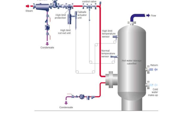
A separate overheat protection system, as shown in Picture 7.2.4, is available to comply with local health and safety regulations or to prevent product spoilage. The purpose of the high limit cut-out device is to shut off the flow of the heating medium in the pipe, thereby preventing overheating of the process. It was originally developed to prevent overheating in domestic hot water services (DHWS) which supply general purpose hot water users, such as hospitals, prisons and schools.However, it is also used for industrial process applications.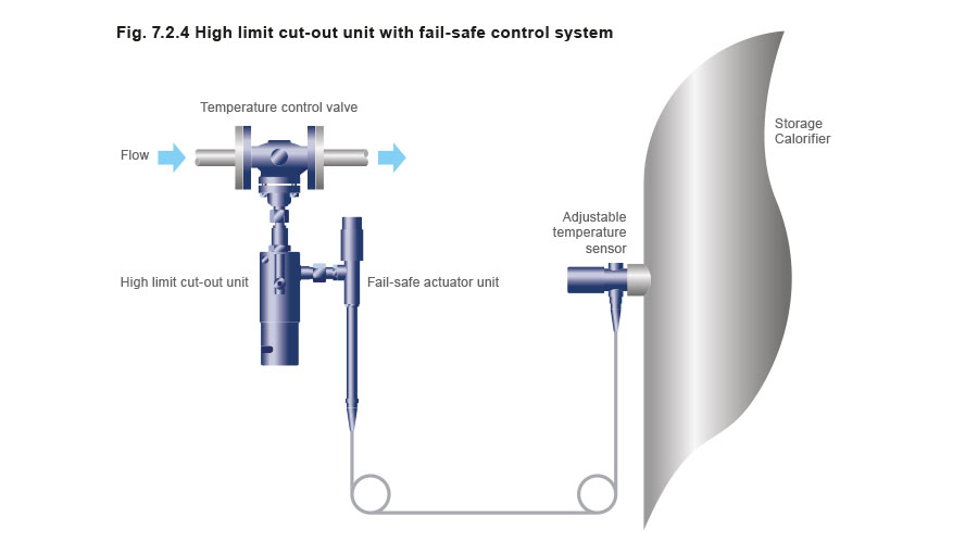
The system is driven by a self-acting control system, which releases a compressed spring in the high limit cut-out unit and snaps the isolating valve shut if the pre-set high limit temperature is exceeded.
The fail-safe actuator unit does not drive the control valve directly, but a shuttle mechanism in the high limit cut-out unit instead. When the temperature is below the set point, the mechanism lies dormant. A certain amount of shuttle travel is allowed for in either direction, to avoid spurious activation of the system.
However, when the system temperature rises above the adjustable high limit temperature, the actuator drives the shuttle, displacing the trigger, which then releases the spring in the high limit cut-out unit. This causes the control valve to snap shut. Once the fault has been rectified, and after the system has cooled below the set temperature, the high limit cut-out can be manually reset, using a small lever. The system can also be connected to an alarm system via an optional microswitch.
The high limit system also has a fail-safe facility. If the capillary is damaged and loses fluid, a spring beyond the shuttle is released, pushing it the other way. This will also activate the cut-out and shut the control valve.
The trigger temperature can be adjusted between 0 ° C and 100 ° C. The fail-safe actuator unit shown in Picture 7.2.5 is only suitable for use with a high limit cut-out unit. The systems shown in Pictures 7.2.1, 7.2.2 and 7.2.3 can also be used with the cut-out unit but they will not fail-safe. Picture 7.2.5 shows the high limit cut-out unit attached to a separate valve to the temperature control valve. This is preferable because the high limit valve remains fully open during normal operation and is less likely to harbor dirt under the valve seat. The high limit valve should be line size to reduce pressure drop in normal use, and should be fitted upstream of the self-acting (or other) control valve and as close to it as possible.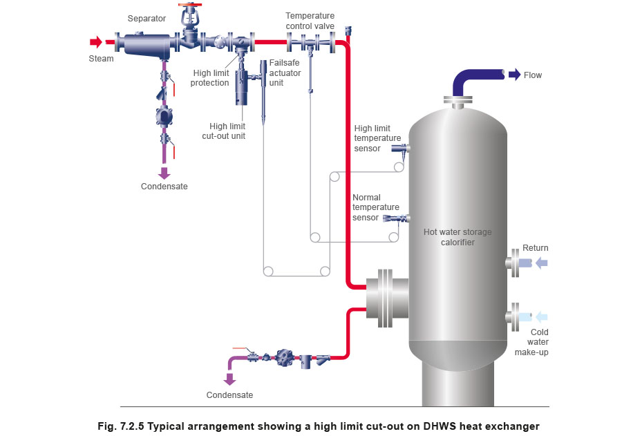
For heating applications, the high limit valve must be fitted in series with the temperature control valve, as shown in Picture 7.2.5. However, in cooling applications, the temperature control valve and high limit valve will both be of the normally-open type and must be fitted in parallel with each other, not in series.
The following valves can be used with the high limit system:
- Two-port valves, normally open for heating systems.
- Two-port valves, normally closed for cooling systems.
- Three-port valves.
Valves having a ball-shaped plug cannot be used with the cut-out unit. This is because the closing operation could drive the ball into the seat and damage the valve.
Also, a double-seated valve should not be used with this system because it does not have tight shut-off.
Typical environments and applications
Environments suitable for self-acting temperature controls:
- Any environment where the sophistication of electrical and pneumatic controls is not required. Especially suited to dirty and hazardous areas.
- Areas remote from any power source.
- For the accurate control of storage or constant load applications, or for variable load applications where high accuracy is not required.
Industries using self-acting temperature controls:
Foods
- Milling, heater battery temperature control (non-hazardous).
- Abattoirs - washing down etc.
- Manufacture of oils and fats - storage tank heating.
Industrial
- Metal plating - tank heating.
- Tank farms - heating.
- Refineries.
- Industrial washing.
- Steam and condensate systems.
- Laundries.
Heating, ventilation and air conditioning (HVAC)
- Domestic hot water and heating services in nursing homes, hospitals, leisure centres and schools,prisons and in horticulture for frost protection.
The most commonly encountered applications for self-acting temperature controls:
Boiler houses
- Boiler feedwater conditioning or direct steam injection heating to boiler feedtank.
- Stand-by generator cooling systems.
Non-storage calorifiers
- 2-port temperature control and overheat protection, (steam or water).
- 3-port temperature control and overheat protection (water only).
- 2-port time / temperature control (steam only).
Storage calorifiers
- 2-port temperature or time/temperature control and overheat protection (steam or water).
- 3-port control and overheat protection (water only).
Injection (or bleed-in) systems
- 2-port or 3-port injection system.
Heating systems
- Basic mixing valve and compensating control.
- Zoned compensating controls.
- Basic compensator plus internal zone controls.
- Control of overhead radiant strip or radiant panels.
Warm air systems
- Heater battery control via room sensor, air-off sensor or return air sensor.
- Compensating control on air-input unit.
- Low limit and high limit control.
- Frost protection to a heater battery.
Fuel oil control
- Bulk tank heating coil control.
- Control of line heaters.
- Control of steam tracer lines.
Process control
- Acid pickling tank.
- Plating vat.
- Process liquor boiling tank.
- Brewing plant detergent tank.
- Drying equipment, for example, laundry cabinet or wool hank dryer, chemical plant drying stove for powder and cake, tannery plant drying oven.
- Continuous or batch process reaction pan.
- Food industry jacketed pan.
Cooling applications
- Diesel engine cooling.
- Rotary vane compressor oil cooler control.
- Hydraulic and lubricating oil coolers.
- Cooling control on cold water to single-stage compressor.
- Closed circuit compressor cooling control.
- Air aftercooler control.
- Air cooler battery control.
- Jacketed vessel water cooling control.
- Degreaser cooling water control.
Special applications
- Control for reducing fireside corrosion and thermal stress in LTHW boilers.
- Hot water cylinder control.
- Temperature limiting.
Applications for the high limit safeguard system
- Preventing temperature overrun on hot water services, or heating calorifiers, in accordance with many Health and Safety Regulations. Good examples include prisons, hospitals and schools. An optional BMS/EMS interface to flag high temperature trip is available.
