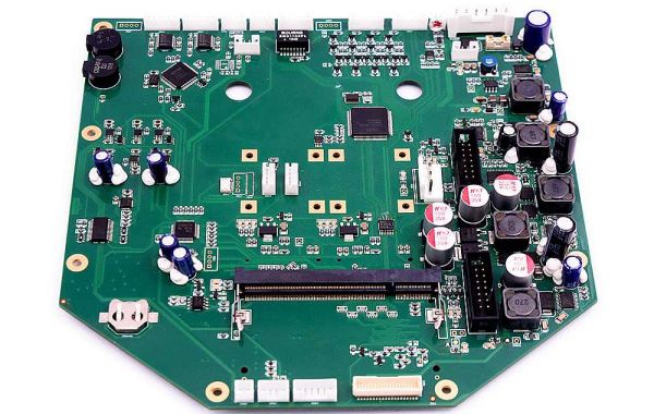
Today, FS Technology demonstrates the basics of circular boxes, from simple introductions to printed circular boxes to complex design systems. Whether you are new to PCB design or want to repeat, FS Technology can easily explain the process in this informative article.
A. What is a printed circuit board?
PCB stands for Publication Committee. If you're familiar with electronic devices, you know that these items serve a variety of purposes.
PCBs are the base material (copper board), materials and other items that are usually sold in cups.
B. There are ten printed circuit boards
1.PCB point PCB
The same thing is behind this. The holes at the top are for mounting parts. Wires are then connected to these plots and sold together.
The design of printed circuit boards in points is complex and often leads to many errors.
2.PCB system
PCB systems are simpler. A printed circuit board design program for landscaping. Designs are printed on brass paper and materials are sold on board.
This approach reduces errors and shortens implementation time.
fs-pcba available
C. Step-by-Step Guide to Screen Printing on Printed Circuit Boards
Step 1: Draw a circle
Run the first program.
After downloading the program, you should see your workspace at the top with all the tools and utilities you can access by swiping from left to right. In the middle is a white rectangle. Draw a circle inside this blue rectangle.
Step 2: Select Update
The material you use will depend on the type of circle you're developing, so we won't discuss specific options at this time.
But there are two things.
Go to the "Libraries" section, then to the "Tools/Bookmarks" section. The selected item will appear in a new window.
Use the tools on the left. Click on the tooltip and select it from the partition library.
The selected location will be displayed in the device list. These devices can be rotated. Use a rotary wrench for this.
When you're ready, you can start adding collaboration elements to your workspace. Once everything is in place, you can use computer signals to make connections between connected objects to create circles.
If you need to edit a partition, right-click on it and the repair option will appear in the download menu.
When the virtual circle is full, save and edit the file.
Step 3: Create a layout for the print screen - open
At this time, a special scheme is used to make the top of the PCB.
You should see a window with an edit list.
To create a screen edge, select 2D Gallery Mode Layers Edge Board.
You can now drag the field to the workspace. Click after the field is drawn and the line (green) turns red. Circles are drawn on the white frame of this phone.
Step 4: PCB System - Construction Equipment
Click on the partitions you want to use, then use the spin button to drag them into the table to spin them.
After all components are installed, install them as needed. To do this, use Mode Selection.
Collect as soon as you're ready. Change text in music mode. Track width depends on the specific PCB design.
Click on the end of the section to connect the section. A green line will appear that you can drag to the other side. After that, the green line will disappear.
printed circuit board layers
Very valuable
You'll see links on the one hand and integrations on the other.
It's two floors
Yes, you can see a symbol with two elements on the side.
There are several steps
Each layer looks a different color: for example, bottom layer - blue, top layer - red, inner layer 1 - purple, etc.
Step 5: Create PCB Layout - Inspection
The black arrow indicates the direction of the stop.
Green line indicates consistency
The blue line represents the weather
Red circles indicate tracking errors
Errors can be avoided by switching modes.
If there are multiple layers on the PCB, you can use the left mouse button to switch tracks between layers. Double click it.
Note that you can use a router. This allows you to set up design and PCB settings before auto-navigation.
After inspection is complete, save the PCB function to a file containing circles, such as Proteus. You can view 3D visuals if necessary.
Step 6: Remove the Landscape
