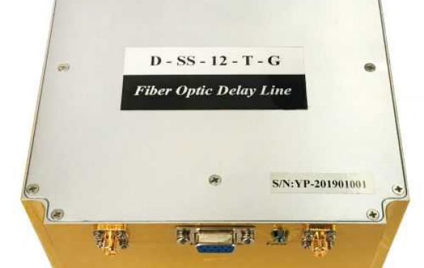
An Optical Delay Line (ODL) is an electric-optic-electric instrument. It performs fixed time delay(s), between a few nanoseconds up to several hundred microseconds, for signals from 10MHz up to 40GHz and more. There are low-frequency ODL versions ranging from 10MHz to 6GHz. The high-frequency ODLs versions are up to 8GHz, 15GHz, 18GHz, 20GHz, and 40GHz.
On a more technical level, the input signal is converted into an optically modulated signal. The optical signal is transmitted into a long single-mode fiber, usually at a 1.55-micron wavelength or similar. Passing the fiber, the optical signal is converted back into an electrical RF signal. The electrical control on the ODL elects the optical system automatically, with no need for any tuning by the operator.
An Optical Delay Line system (ODL) also incorporates high-performance lasers such as DFBs, optical modulators for high operation frequencies, photodiodes, and optionally other components such as optical dispersion compensators, optical switches, optical amplifiers, and pre-and-post NEON amplifiers to provide exceptionally high performance. The ODL optical system supports very high bandwidths of analog signals, high sensitivity with a wide dynamic range, for various delays.
Variable Optical Delay Lines (also known as Progressive ODLs) are used in a variety of applications including radar range simulation and signal processing. The Progressive ODL has a few delay lines using the same transceiver where the customization is done.
The most common practical approach for a variable delay system is an ODL system configuration which includes cascaded 1:2 and 2:2 optical matrices with several different delay lines in between (replacing the above two optical switch matrix 1:8). This cascaded switch matrix is a Progressive Delay Configuration which is shown below.
The desired combination of delay lines is selected to define the required delay. In the diagram below, there are 4 progressive delay lines with cascaded switch matrices. In such a configuration, the user can select any of the 16 combinations of possible delay values (16=24). For example, a delay can be selected which is equivalent to Dtot= D1+D2 +D4, or Dtot= D3+D4 etc.)
Progressive Optical Delay Line configuration consisting of four 2:2 optical switch, providing 16 different delay lengths.
Sometimes, dispersion compensation is needed when the signal frequency and the delay line length increase, resulting in the optical signal to be dispersed and weakened significantly. As NEON, we solve this problem by incorporating DCM (Dispersion Compensation Module) in our Optical Delay Line (ODL) solutions.


