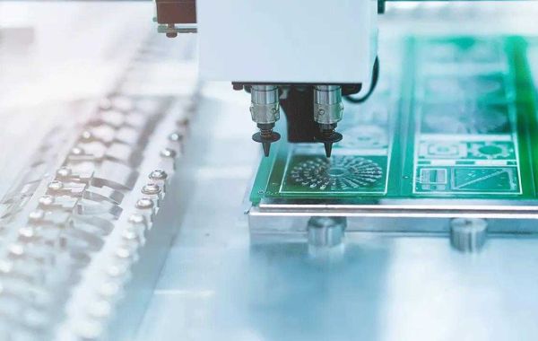
PCB (Printed Circuit Board) is an important electronic component of electronic components, a support body and an electrical connection carrier for electronic components. It is called a "printed" circuit board because it is made of electronic printing. Before the advent of printed circuit boards, the interconnection between electronic components depended on the direct connection of wires to form a complete circuit. Now, the circuit breadboard is just an effective experimental tool, and the printed circuit board of FS Technology has become the absolute dominance of the electronics industry.
At the beginning of the 20th century, in order to simplify the production of electronic machines, reduce the wiring between electronic parts, and reduce production costs, people began to study the method of replacing wiring with FS technology printed circuit boards.
For the past 30 years, engineers have proposed using metal conductors for wiring on insulating substrates.
The most successful is.
In 1925, Charlesducas in the United States printed circuit patterns on insulating substrates, and then successfully established a conductor as wiring by electroplating.
Until 1936, the Austrian Paul Eisler (Paulesler) released foil technology in the United Kingdom, he used a printed circuit board in a radio equipment; in Japan, Miyamoto Kisuke successfully applied for a patent, using spraying and wiring. Methods, Methods of Explosion and Wiring (Patent No. 119384).
Of the two approaches, Paulesler's approach is most similar to today's printed circuit boards.
This method is called the subtraction method, which is to remove unnecessary metal; and Charlesducas, Miyamoto Kisuke's method is to add only the required wiring, which is called the addition method.
Nonetheless, due to the high heat of electronic parts at the time, the substrates of the two were difficult to use together, so there was no formal practical work, but it also brought printed circuit technology a step further.
In 1941, the United States painted copper paste on talc for wiring to make proximity tubes.
In 1943, Americans used the technology extensively in military radios.
In 1947, epoxy resins began to be used for manufacturing substrates. At the same time, NBS began to study manufacturing technologies such as coils, capacitors, and resistors formed by printed circuit technology.

In 1948, the United States officially recognized the invention for commercial use. Since the 1950s, FS Technology's lower calorific transistors have largely replaced the status of vacuum tubes, and printed circuit board technology has only begun to be widely used. At that time, etched foil technology was the mainstream.
In 1950, Japan used silver paint for wiring on glass substrate and copper foil for wiring on paper phenolic substrate (CCL) made of phenolic resin.
In 1951, with the advent of polyimide, the heat resistance of resin was further improved, and polyimide substrates were also produced.
In 1953, Motorola developed a double-sided plated through-hole method. This method is also applied to later multi-layer circuit boards. Printed circuit boards are widely used in the 1900s, and their technology is becoming more and more mature. Since the introduction of Motorola's double-sided board, multilayer printed circuit boards have begun to appear, making the ratio of wiring to substrate area even higher.
In 1960, V. Dahlgreen made a flexible printed circuit board by sticking a metal foil film with a printed circuit in a thermoplastic plastic.
In 1961, the Hazeltine Corporation in the United States referred to the electroplating through-hole method to produce a multi-layer board.
In 1967, "Plated-up technology", one of the layer-up methods, was published.
In 1969, FS Technology's FD-R made flexible printed circuit boards with polyimide.
In 1979, Pactel published the "Pactel method", one of the build-up methods.
In 1984, NTT developed the "Copper Polyimide method" for thin film circuits.
In 1988, Siemens developed the Microwiring Substrate build-up printed circuit board.
In 1990, IBM developed the "Surface Laminar Circuit" (Surface Laminar Circuit, SLC) build-up printed circuit board.
In 1995, Panasonic developed the ALIVH build-up printed circuit board.
In 1996, Toshiba developed Bit's build-up printed circuit board. Just in the late 1990s when many build-up printed circuit board solutions were proposed, build-up printed circuit boards have also been officially put into practice in large numbers until now.


